Creating detailed drawings of computer systems needs both art and tech knowledge. This step-by-step guide helps you make professional diagrams. These show modern computing hardware clearly.
Technical illustrations are key in education, tech docs, and presentations. Learning these skills helps share complex hardware ideas with many people.
We’ll teach you about key parts like monitors, keyboards, and system units. You’ll get better at drawing with our method. We’ll also show you how to avoid mistakes that make diagrams unclear.
This guide is great for students, teachers, and tech artists wanting to improve their hardware drawing skills. The methods here will help you make detailed, correct pictures of computer systems.
Essential Drawing Materials and Tools
To make accurate computer system diagrams, you need the right drawing materials and tools. The best tools help you achieve professional results, whether you use traditional or digital methods.
Choosing between traditional and digital tools depends on what you like and what your project needs. Both ways have their own benefits for technical illustrations.
Traditional Drawing Supplies
Quality drawing pencils are key for traditional technical drawing. You’ll need pencils from HB to 4B for both light sketches and darker lines.
Precision rulers are vital for straight edges and accurate measurements. Metal rulers are better than plastic for clean lines.
Good erasers are essential for fixing mistakes without ruining the paper. Kneaded erasers are great for gentle corrections, while vinyl erasers are better for thorough removal.
Choose drawing paper that’s around 120gsm for erasing and ink work. Look for smooth surfaces for the best technical diagrams.
Fine-line pens are needed for permanent technical details. Brands like Rotring or Staedtler offer reliable pens for professional results.
Digital Drawing Options
Graphic tablets make computer drawing feel natural. Wacom tablets are top choices for their reliability and pressure sensitivity.
There are many stylus options, from basic to professional. Some styluses have tilt recognition and multiple pressure levels for detailed control.
Software applications offer powerful tools for computer illustration. Free options like Krita or GIMP are great for beginners.
Professional software like Adobe Illustrator or CorelDRAW has advanced features. These programmes are perfect for technical drawings with precise vector tools.
Digital tools make it easy to correct and adjust your work. Layers and undo functions let you try out different layouts without worry.
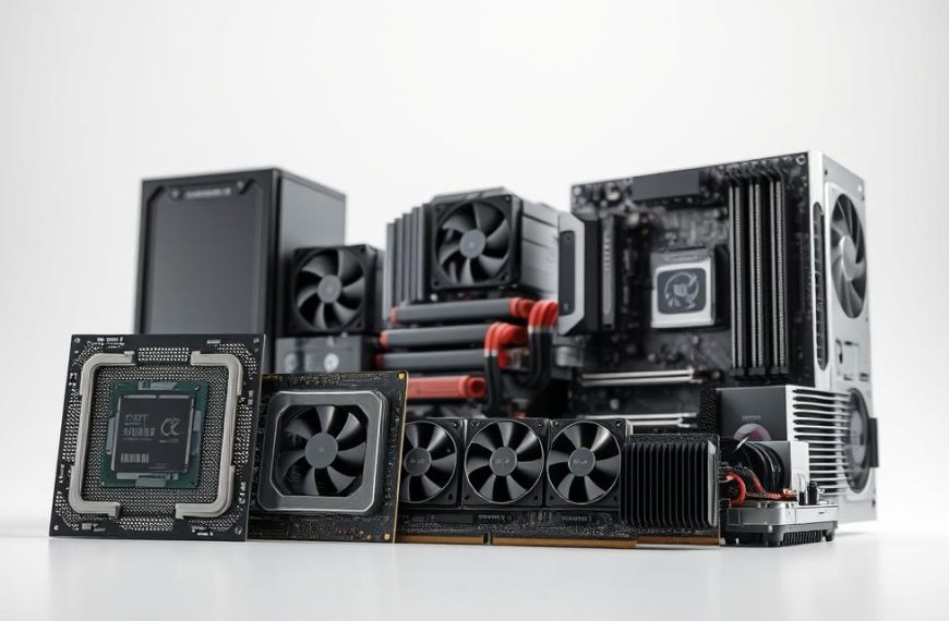
Understanding Computer System Components
Before starting any hardware sketching, artists need to know the basics of a computer’s inside. This knowledge is key for making precise technical drawings that show computer anatomy well. Each part has its own look that artists should highlight for both accuracy and beauty.

Central Processing Unit (CPU)
The CPU is the computer’s brain, looking like a small square or rectangle. It has a metallic top with the maker’s logo. When drawing the CPU, focus on its exact spot in the socket and the direction of the alignment markers.
Notice the tiny texture on the heat spreader and the layout of the contact pins underneath. These details are vital for showing the CPU both in place and as a separate part in exploded views.
Motherboard and Expansion Cards
The motherboard is like the computer’s main nerve system, connecting all parts. It’s a green or black PCB with lots of circuitry and connection points. Key things to draw include the CPU socket, RAM slots, and expansion slots.
Expansion cards, like graphics or sound cards, add extra features. They have heat sinks, fans, and ports. When drawing these, pay attention to their size compared to the motherboard and how they connect.
Memory and Storage Devices
RAM modules are long, thin sticks with circuitry on one side and notches for fitting right. Storage devices vary – hard drives have metal cases with labels, while SSDs are smaller and simpler.
Artists should show the different shapes and how they connect. Hard drives use SATA, while SSDs plug straight into the motherboard. These differences are key for hardware sketching.
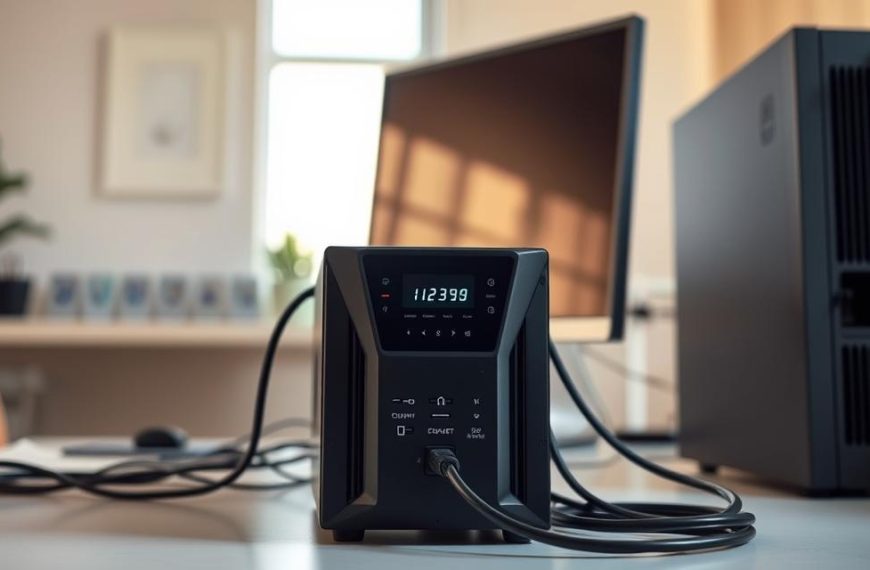
Power Supply and Cooling Systems
The power supply unit (PSU) looks like a metal box with many cable ports and vents. Its size and cable setup change based on its power and design. Cooling systems range from simple heat sinks to complex air or liquid setups.
Air cooling has fans with unique blades and mounts. Liquid cooling has reservoirs, tubes, and radiators that need careful scale and layout. These add interest to computer diagrams.
When drawing cooling systems, focus on airflow and thermal interaction. This makes diagrams that are both useful and visually appealing for computer anatomy.
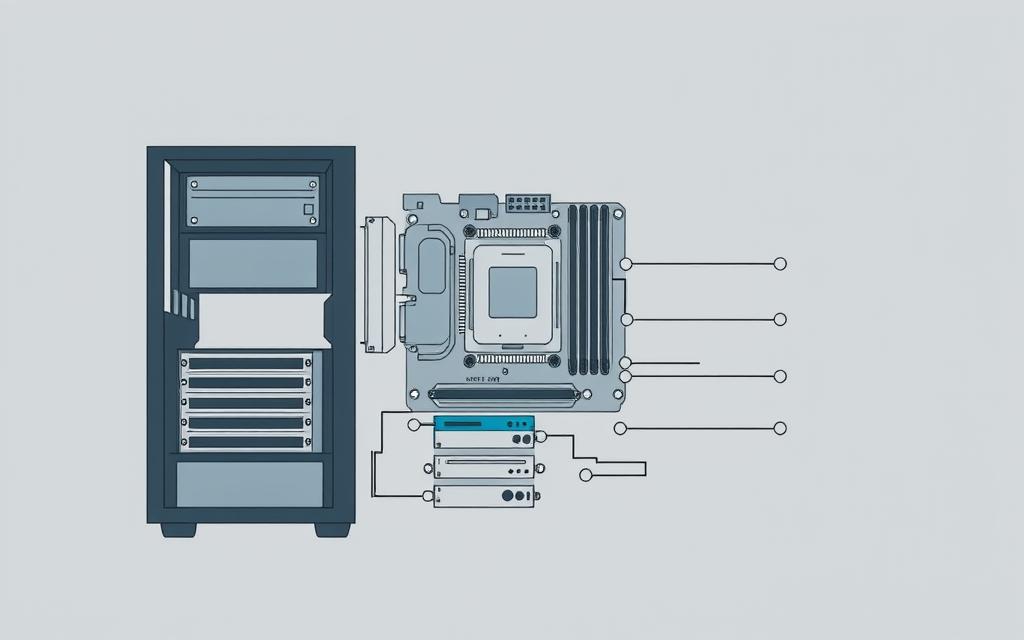
Planning Your Computer System Diagram
Before you start drawing, think about how people will see your diagram. It’s important to plan well to show how parts work together clearly. This step makes your drawings look professional.
Choosing the Right Perspective
Choosing the right angle is key. Different angles are good for different things. Think about what you want to show with your perspective drawing.
The front view is good for simple diagrams. It shows what users see. Side views are better for showing how parts fit together.
Isometric views give a 3D feel. They show depth and keep proportions right. This is great for detailed tech drawings.
Try drawing quick sketches from different angles. See how each view shows different things. Pick the angle that best fits your diagram’s purpose.
Establishing Proper Scale and Proportions
Getting the size and shape right is important. Parts need to look like they do in real life. Start by looking up the real sizes of computer parts.
Use sizes from the makers’ specs. For example, an ATX motherboard is 305 × 244 mm. Use this as a guide for other parts.
Keep the same scale for everything. If you make one part smaller, make all parts smaller by the same amount. This keeps things in proportion.
Practice by drawing two shapes to represent parts. Make them the right size compared to each other. Use a ruler for straight lines and to measure.
| Perspective Type | Best Use Case | Complexity Level | Component Visibility |
|---|---|---|---|
| Front View | Basic Education | Beginner | External Components Only |
| Side View | Layer Relationships | Intermediate | Partial Internal View |
| Isometric View | Technical Documentation | Advanced | Complete 3D Representation |
| Exploded View | Assembly Instructions | Expert | All Components Separated |
Planning helps a lot when you’re drawing in detail. Try out different ways before you decide. Good planning makes your diagrams clear and accurate.
How to Draw a Computer System: Basic Framework
Creating the basic structure needs careful planning and precise techniques. This stage sets the visual base for your computer system diagram. A well-built framework makes your drawings look professional.

Technical illustrators stress starting with light lines. These lines help make changes before finalising the outline. The framework focuses on how things are arranged, not on details.
“A successful technical illustration starts with a solid framework. It must show the subject’s size and how things are related.”
Creating the Main Chassis Outline
Computer cases vary in shape, each needing a different drawing method. Standard ATX towers have a rectangular shape with set proportions. Smaller cases need careful attention to size while keeping key features.
Start with basic shapes that fit your case type. Use straight edges and rulers for sharp lines. Focus on corner angles and keeping perspective the same throughout.
The table below shows common computer case types and their key drawing characteristics:
| Case Type | Primary Shape | Proportion Ratio | Drawing Difficulty |
|---|---|---|---|
| Full Tower | Rectangular prism | 2:1:1 (H:W:D) | Medium |
| Mid Tower | Rectangular prism | 1.5:1:1 | Easy |
| Mini-ITX | Square prism | 1:1:1 | Medium |
| Cube Case | Perfect cube | 1:1:1 | Hard |
Positioning Major Components
Components are placed in a logical order, like in real systems. The motherboard is usually the biggest part. Place it first, as other parts depend on it.
Power supply units go in corners, depending on the case. Storage devices fit in drive bays at the front. Make sure there’s enough space for airflow and cable management.
Use light crosshairs or marks to show where components go before drawing them in detail. This helps keep your drawing balanced and accurate. Remember, internal parts must match up with external ports and connectors.
Good technical illustration needs to understand both visual and technical aspects. The framework stage is key for adding detailed parts in later steps.
Detailed Component Drawing Techniques
Mastering computer system illustration needs precise techniques for each component. This section looks at special ways to draw key hardware parts accurately.
Drawing the Motherboard and CPU
Start with the motherboard’s rectangular PCB outline. Use green or black for the substrate. Place the CPU socket in the middle.
For Intel, draw the retention lever and alignment notches. AMD sockets need a pin grid array pattern.
Use parallel lines for heat sink fins with even spacing. Show thermal pipes as curved cylinders. Include power delivery components around the socket.
Illustrating Storage Devices and Memory
Hard disk drives have rectangular metal casings with rounded corners. Add SATA connectors on one end. SSDs are slimmer with NAND flash chips under a sticker.
RAM modules are long and narrow. Draw gold contact fingers and heat spreaders. DIMM slots must align with these modules.
Key differences to capture:
- HDDs have thicker 3.5-inch form factors
- SSDs use 2.5-inch or M.2 designs
- RAM modules include notch positions for proper orientation
Rendering Power Supply and Cables
Start with the PSU’s square or rectangular metal casing. Add a fan grill on one side. Show the power input socket and switch on the rear panel.
For cable management, draw bundles from the PSU in organised groups. Use curved lines for cables. Differentiate cable types by thickness:
- 24-pin ATX cable: thickest bundle
- PCIe power cables: medium thickness with distinct connectors
- SATA power: flat ribbon-style cables
Component visualisation is more convincing with these details. Each element makes the diagram both accurate and appealing.
Adding Realistic Details and Textures
To make your computer system diagram look professional, you need to add realistic details and textures. These details make your drawing come alive and share important technical info clearly.
Creating Metallic Surfaces and Finishes
Computer parts have different finishes that need special drawing skills. Brushed aluminium needs soft lines and gentle highlights. Painted steel, on the other hand, looks best with even shading and sharp reflections.
For plastic parts, use gentle gradients and few reflections. Motherboards mix materials, so pay close attention to how light hits each part.

| Material Type | Shading Technique | Highlight Method | Common Applications |
|---|---|---|---|
| Brushed Aluminium | Parallel line patterns | Soft linear highlights | Case panels, heat sinks |
| Painted Steel | Uniform gradient fills | Sharp reflective spots | Chassis framework, brackets |
| Plastic Components | Soft shadow transitions | Diffused light effects | Connector housings, buttons |
| PCB Surface | Textured pattern overlay | Minimal reflection | Motherboard, expansion cards |
Drawing Connectors and Ports
Getting connectors and ports right adds credibility to your diagram. Each type has its own look that needs to be drawn accurately.
USB ports are rectangular with internal lines. HDMI connectors are trapezoidal with pin details. Audio jacks are circular with a centre dot for pin representation.
Make sure port spacing and alignment are correct. While most systems follow standards, some manufacturers vary. Always check technical specs for the best accuracy.
Adding Labels and Annotations
Good labelling makes your drawing educational. Use clear, sans-serif fonts that are easy to read, even when small.
Put labels in places that don’t clutter the drawing. Use leader lines when needed, keeping them simple and organised. Group similar annotations to help the viewer understand better.
Try a systematic labelling method for consistency. This keeps your diagram clear and visually appealing.
Include both component names and key specs in your annotations. This turns your diagram into a detailed technical guide.
Common Drawing Mistakes and How to Avoid Them
Even skilled artists face challenges when drawing computer systems. Spotting common errors helps avoid them. This keeps your diagrams accurate and professional.

Proportional Errors
Scaling mistakes are a big problem. Artists often get the sizes of parts wrong. This makes some parts look too big or too small.
To get the scale right, use measurements for each part. Make a size chart before you start drawing. This helps keep everything consistent.
Perspective can also cause problems. Angled views can distort parts if perspective lines are off. Use lines and vanishing points to keep things right.
| Common Proportional Error | Visual Effect | Prevention Strategy |
|---|---|---|
| Oversized CPU relative to motherboard | Unrealistic component relationship | Use manufacturer specifications for size ratios |
| Incorrect drive bay proportions | Storage devices won’t fit chassis | Measure actual components before drawing |
| Distorted perspective on angled views | Components appear warped or bent | Establish consistent vanishing points |
| Inconsistent scaling between components | Diagram lacks technical credibility | Create a scaling reference chart beforehand |
Component Placement Issues
Artists sometimes place parts in ways that don’t work. Overlapping parts that need space is a common mistake.
Motherboard placement errors happen often. Always check manuals for how to mount it right.
Cable routing mistakes can make diagrams messy. Don’t let cables block airflow or go through solid parts.
Storage device errors include wrong placement or orientation. Hard drives usually mount with connectors facing inwards.
Technical Accuracy Considerations
Getting connector types wrong can hurt accuracy. Different ports look similar but have unique specs.
Mounting parts in the wrong place is another error. Expansion cards and power supplies need to be in the right spots.
Cooling system mistakes can make your drawing look off. Fans should show airflow direction, and heat sinks should be the right size.
Compatibility issues happen when parts don’t work together. Check specs to make sure your drawing is possible.
By fixing these mistakes early, you can make diagrams that look good and are technically correct.
Conclusion
Creating accurate computer system diagrams needs both technical know-how and artistic flair. Knowing about computer parts is key to making good technical drawings. How well you show motherboards, CPUs, and storage devices matters a lot.
Practising regularly helps you find your style while keeping things accurate. Try out different computer setups to get better. Using advanced techniques like exploded views shows how parts work together. Schematic diagrams with electrical paths are the next step for experts.
These drawing skills are useful in many areas. They make educational materials clearer and more engaging. They’re also vital for creating detailed technical documents. Plus, they’re needed for professional illustration work that looks good and is precise.
Keep improving your skills in drawing computer systems. Every drawing you do helps you understand technology better. As you get better, you’ll be ready to handle more complex systems with ease.
FAQ
What drawing tools are essential for creating a professional computer system diagram?
For traditional drawing, you’ll need quality supplies. This includes HB to 4B pencils, precision rulers, erasers, and fine-line pens. For digital work, graphic tablets and a stylus are key. Adobe Illustrator or free options like Inkscape are good software choices.
Brands like Wacom for tablets and Rotring for pens often give the best results.
How do I choose the right perspective for my computer system diagram?
The perspective you choose depends on your diagram’s purpose. A front or side view is great for teaching. An isometric view is better for detailed, three-dimensional tech drawings.
Think about who will see your diagram and how much detail they need.
What are the key components I need to understand before drawing a computer system?
Understanding the CPU, motherboard, and expansion cards is key. Also, memory (RAM), storage devices, the power supply unit (PSU), and cooling systems are important. Knowing how they fit together is essential for a clear diagram.
How can I ensure proper scale and proportions in my diagram?
Use real measurements or technical specs to get the scale right. Plan your diagram with a consistent scale and sketch out lines to show how things fit together. Drawing from real hardware or photos helps keep sizes accurate.
What techniques help in rendering realistic metallic surfaces and textures?
To get metallic surfaces right, use shading and highlighting that matches the material. For example, use soft gradients for brushed aluminium and sharp contrasts for glossy finishes. Think about light sources and reflections, and use digital brushes that mimic textures.
What common mistakes should I avoid when drawing computer systems?
Avoid mistakes like wrong sizes or bad perspective. Make sure components fit logically and are technically correct. Check your work against real hardware or reliable sources to avoid mistakes.
Are there recommended software tools for digital illustration of computer systems?
Yes, Adobe Illustrator and CorelDRAW are top choices for their precision. Free options like Inkscape and GIMP also work well. Using a graphic tablet from Wacom or Huion adds to the detail.
How important are labels and annotations in a computer system diagram?
Labels and annotations are very important. They explain what each part does and highlight key components. Use clear fonts, place them well, and keep information organised for a professional look.
Can I use this guide for drawing both traditional and digital diagrams?
Yes, this guide is for both traditional and digital drawing. The main points of accuracy, proportion, and detail are the same. But, the tools and methods differ, so you can create professional work in your preferred medium.
What is the benefit of practising with different computer configurations?
Practising with different setups improves your skills. It helps you work on various projects, from standard desktops to special systems. This broadens your technical and artistic abilities.

 By
By